PON Passive Network Design Principles
PON stands for Passive Optical Network, and the term itself is a bit misleading. After all, the AON/P2P topology we have seen before is also completely passive. When talking about PONs in this context we mean a passive distribution layer where the aggregate subscribers with the use of passive splitters, to share one fiber between multiple subscribers. These splitters are simple power splitters with 1 input and 2^n outputs, distributing the input signal to multiple outputs, and in the reverse direction combining the signals on one fiber.
This will of course impact the optical power budget. Each 1:2 split adds an approximate loss of 3 dB, so for example a 1:16 splitter will introducte 12 dB loss for splitting only. This needs to be taken into account when deciding on split ratios and positions of active network equipment.
From AON to PON
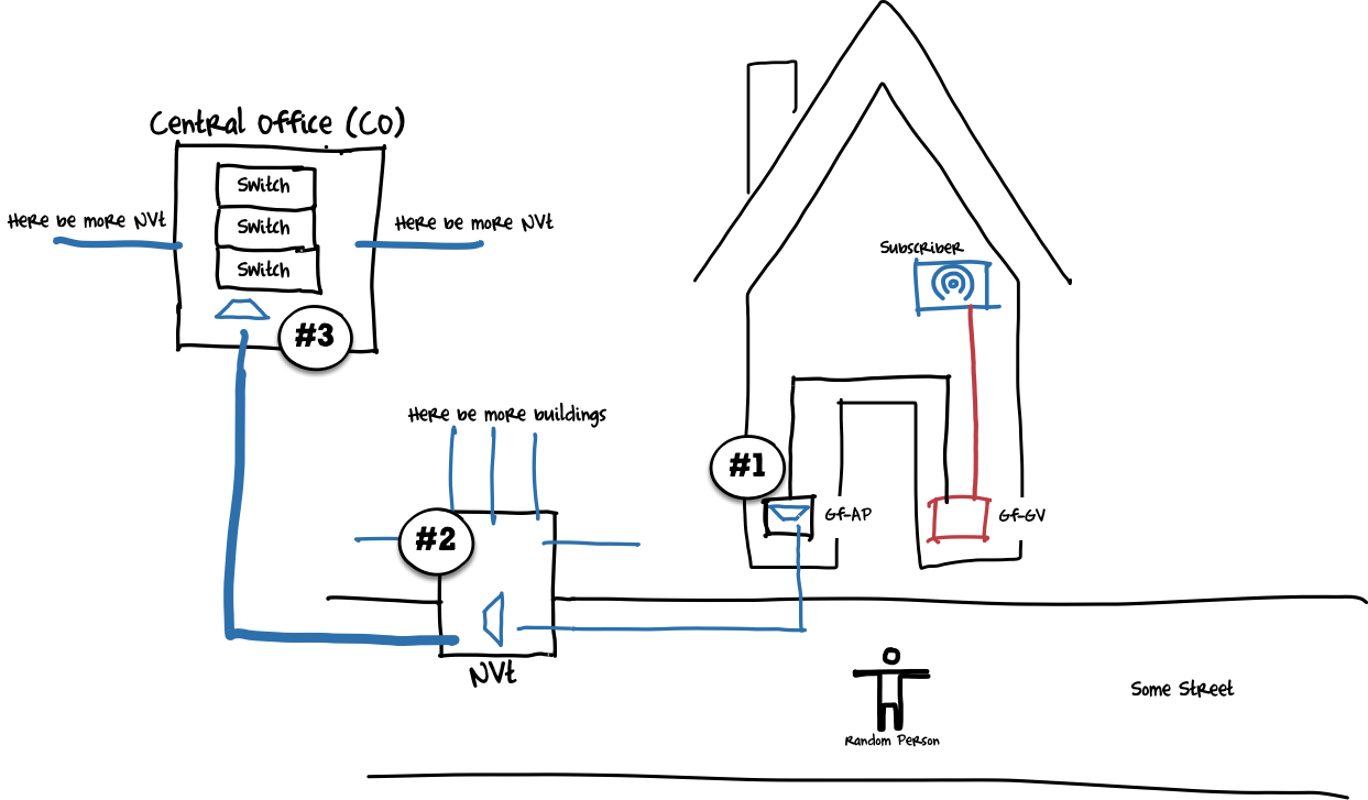
As mentioned before, the topology of an AON is the base design for all fiber networks, since it is the most versatile. So we are starting with the AON topology we have seen before, and convert it into a PON topology:
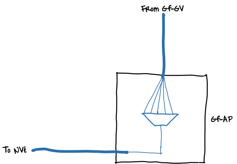
Placement of Splitters
The most common places for splitters are in the Gf-AP (#1) inside the building, to aggregate the subscribers in this building, and in the NVT (#2) to aggregate multiple buildings onto one fiber going to the CO. You could potentially use splitters anywhere (for example in the CO, #3), but it makes most sense in distribution points where you already terminate fibers on patch connections.
As we discussed before, splitters add additional loss and subscribers share one fiber - both are usually not desirable effects in a network. What are the upsides of splitters then? Let’s go through a small example deployment. The main focus here is the number of fibers we use on each cable.
Effect of Splitters on Network Capacity
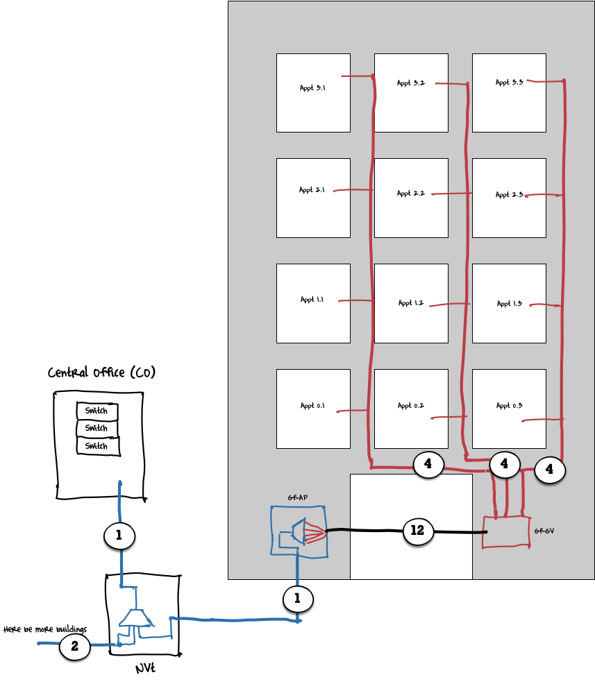
We have a building with 12 apartments, so 12 fibers with active subscribers terminate in the Gf-GV, 4 from each staircase. We are patching them through to the Gf-AP and are using 12 fibers as well on the connection between Gf-GV and Gf-AP. Here we are now installing a 1:16 splitter, so those 12 fibers are connecting all to the splitter and will go out on one fiber towards the NVt. In the NVt we are combining fibers from other buildings on yet another splitter, and again will only use one fiber going to the CO.
So just for this one example, all 12 apartments share the same fiber towards the NVt, where more subscribers will be put onto one fiber going to the CO, thus reducing the number of fibers we need in each hop.
Summary
As we mentioned before, subscribers will share the same fiber, and also the bandwidth on this fiber. Also the fiber carrier decides the transmission standard(s) on this fiber and has full control over the lit fiber. It has also become a lot harder to passively hand over a single end customer to a carrier with the PON design.
On the other hand, we have significatly reduced the number of fibers we need to handle in a Gf-AP, in a NVt and in a CO compared to an AON topology. Also due to the lower fiber usage we can extend the passive network and use less aggregation points with active network equipment.
To balance those parameters is the hard part of a PON topology. Economically we want to aggregate as many subscribers as possible on one fiber, technically we want each subscriber to have their own fiber.