Network Design AON/P2P
At the beginning we are looking at AON (Active Optical Network) or P2P (Point-to-Point) network designs, since those are the base design for all fiber networks.
Before we are progressing further, a short shout-out to the german telco world, and an apology to the non-german speaking part of the world who stumbled upon this article. Some acronyms I will be using here are coming from the german telco world, which was heavily influenced by Bundespost and Deutsche Telekom, so they are German acronyms and not easily translated into English. I will try to keep it as generic as possible, but you will encounter a few German compound nouns along the way. Enjoy the ride.
Fiber inside the building
Let’s trace the fiber back from the subscriber to the first active network device: the subscriber is in their apartment and has a home router providing access to their devices at home, in Germany this is in many cases a Fritzbox. This router is connected to a fiber coming into their apartment (#1).
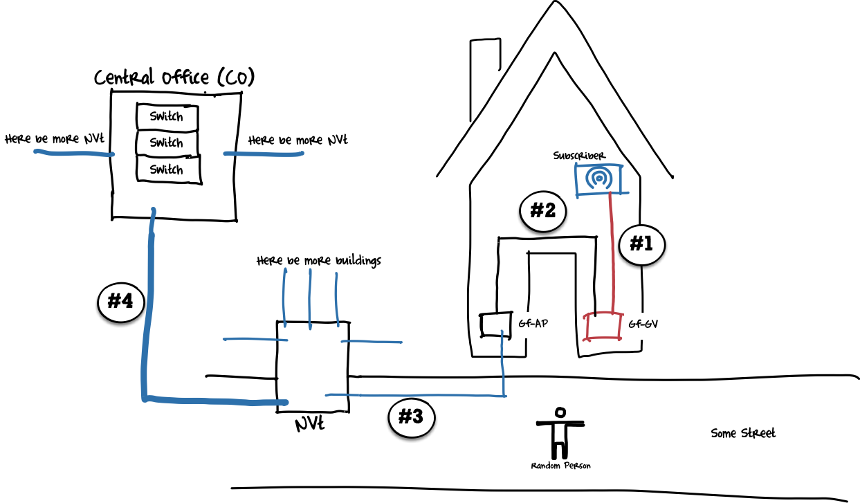
This fiber is the beginning of the fiber network, usually there would be a cable (or a partition of a cable) going into each apartment with more than one fiber, from which one is used to connect the subscriber. The other ones are kept as spare in case one fiber breaks or the customer requires more services. The cable usually terminates in a utility room in the basement in a fiber termination box we call Gf-GV (Glasfaser-Gebäudeverteiler/Building Fiber Termination Box).
This termination box collects all fibers from the building and provides clear termination point. The next stop in our fiber network is the Gf-AP, another fiber termination box which stands for Glasfser-Abschlusspunkt/Fiber Termination Point. This is usually the first element under the sole responsibility of the fiber provide. It is located in the basement as well and holds the fiber coming from outside of the building.
The connection between the Gf-AP and the Gf-GV (#2) can have various forms, depending on the requirements of the fiber network provider. Some sensible options:
-
Both are terminated in the same termination box, with patches between the fiber going to the apartment and the fiber going to the next stop outside of the building
-
The Gf-AP is mounted as close as possible to the entrance of the fiber cable from the street, and then a fiber cable is used between the Gf-AP and the Gf-GV, and the patching will happen on both ends
Fiber aggregation points on street level
With this patching done, we are now exiting the building (#3). The next location where the fiber is going to is street cabinet called NVt (Netzverteiler/Network Distribution Point).
NVts hold multiple cables coming from the neighbouring buildings, and also cables connecting the NVt to the next aggregation point (#4). Depending on the desired network topology, multiple NVts can be daisy-chained and used as larger and larger aggregation points, or you could go from one NVt directly to a central aggregation point where find the first active network devices, as it is done here.
Final aggregation node
However, at some point it doesn’t make sense to aggregate the fibers further, and then we will add an active aggregation point, holding active network equipment. In a surprising change in naming policy, we will call this location Central Office (CO).
Here the journey of the passive fiber network ends, and the active network starts. One last pair of terms from fiber networks are feeder and drop cables.
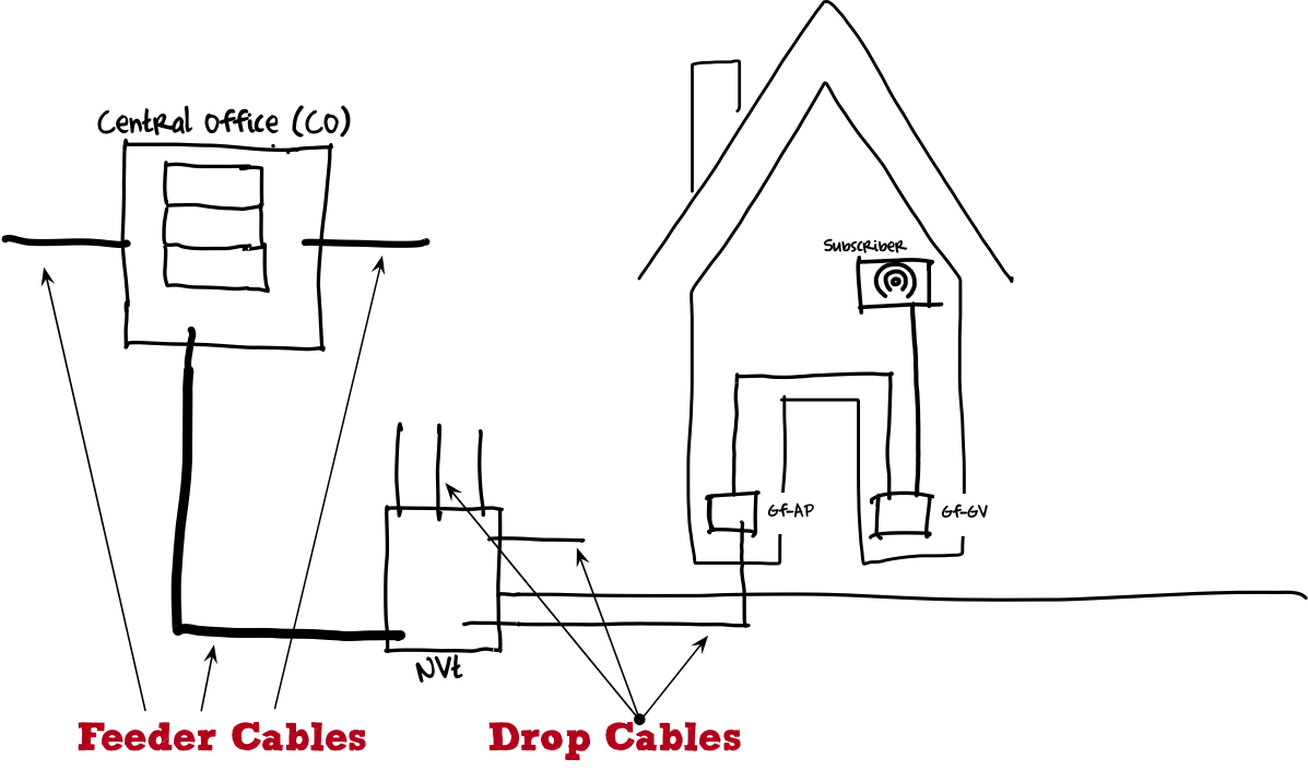
Drop cables are coming from a NVt and going into houses, while feeder cables start at the NVt and going towards the CO. Feeder cables hold more fibers and are aggregating drop cables from the houses towards the CO.
Summary
Now we have a complete picture of the fiber network. When designing such a network, economics and logistics of handling many fiber cables at once are coming into play, so the main question network designers are concentrating on here is: how far can the passive network be build before it becomes either too expensive or too complicated to handle all those fibers. Or, to put the question another way: Where should we put the first active network device and terminate the subscribers.
Before we are dealing with this, however, we will be looking at PON and how it changes the AON topology.